| Symbol |
Description |
Units |
| AC |
Heating coil surface area |
m2 |
| ACmax |
Maximum surface area of coil |
m2 |
| Ain |
Surface area over which heat is transferred in |
m2 |
| Aout |
Surface area over which heat is transferred out |
m2 |
| AP |
Phase change material surface area |
m2 |
| AR |
Aspect ratio |
-- |
| ARmax |
Maximum aspect ratio |
-- |
| ARmin |
Minimum aspect ratio |
-- |
| C |
Specific heat capacity |
\(\frac{\text{J}}{\text{kg}{}^{\circ}\text{C}}\) |
| CL |
Specific heat capacity of a liquid |
\(\frac{\text{J}}{\text{kg}{}^{\circ}\text{C}}\) |
| CS |
Specific heat capacity of a solid |
\(\frac{\text{J}}{\text{kg}{}^{\circ}\text{C}}\) |
| CV |
Specific heat capacity of a vapour |
\(\frac{\text{J}}{\text{kg}{}^{\circ}\text{C}}\) |
| CPL |
Specific heat capacity of PCM as a liquid |
\(\frac{\text{J}}{\text{kg}{}^{\circ}\text{C}}\) |
| CPS |
Specific heat capacity of PCM as a solid |
\(\frac{\text{J}}{\text{kg}{}^{\circ}\text{C}}\) |
| Ctol |
Relative tolerance for conservation of energy |
-- |
| CW |
Specific heat capacity of water |
\(\frac{\text{J}}{\text{kg}{}^{\circ}\text{C}}\) |
| CWmax |
Maximum specific heat capacity of water |
\(\frac{\text{J}}{\text{kg}{}^{\circ}\text{C}}\) |
| CWmin |
Minimum specific heat capacity of water |
\(\frac{\text{J}}{\text{kg}{}^{\circ}\text{C}}\) |
| CPLmax |
Maximum specific heat capacity of PCM as a liquid |
\(\frac{\text{J}}{\text{kg}{}^{\circ}\text{C}}\) |
| CPLmin |
Minimum specific heat capacity of PCM as a liquid |
\(\frac{\text{J}}{\text{kg}{}^{\circ}\text{C}}\) |
| CPSmax |
Maximum specific heat capacity of PCM as a solid |
\(\frac{\text{J}}{\text{kg}{}^{\circ}\text{C}}\) |
| CPSmin |
Minimum specific heat capacity of PCM as a solid |
\(\frac{\text{J}}{\text{kg}{}^{\circ}\text{C}}\) |
| D |
Diameter of tank |
m |
| E |
Sensible heat |
J |
| EP |
Change in heat energy in the PCM |
J |
| EW |
Change in heat energy in the water |
J |
| EPmeltinit |
Change in heat energy in the PCM at the instant when melting begins
|
J |
| g |
Volumetric heat generation per unit volume |
\(\frac{\text{W}}{\text{m}^{3}}\) |
| Hf |
Specific latent heat of fusion |
\(\frac{\text{J}}{\text{kg}}\) |
| Hfmax |
Maximum specific latent heat of fusion |
\(\frac{\text{J}}{\text{kg}{}^{\circ}\text{C}}\) |
| Hfmin |
Minimum specific latent heat of fusion |
\(\frac{\text{J}}{\text{kg}{}^{\circ}\text{C}}\) |
| h |
Convective heat transfer coefficient |
\(\frac{\text{W}}{\text{m}^{2}{}^{\circ}\text{C}}\)
|
| hC |
Convective heat transfer coefficient between coil and water
|
\(\frac{\text{W}}{\text{m}^{2}{}^{\circ}\text{C}}\)
|
| hCmax |
Maximum convective heat transfer coefficient between coil and water
|
\(\frac{\text{W}}{\text{m}^{2}{}^{\circ}\text{C}}\)
|
| hCmin |
Minimum convective heat transfer coefficient between coil and water
|
\(\frac{\text{W}}{\text{m}^{2}{}^{\circ}\text{C}}\)
|
| hmin |
Minimum thickness of a sheet of PCM |
m |
| hP |
Convective heat transfer coefficient between PCM and water |
\(\frac{\text{W}}{\text{m}^{2}{}^{\circ}\text{C}}\)
|
| hPmax |
Maximum convective heat transfer coefficient between PCM and water
|
\(\frac{\text{W}}{\text{m}^{2}{}^{\circ}\text{C}}\)
|
| hPmin |
Minimum convective heat transfer coefficient between PCM and water
|
\(\frac{\text{W}}{\text{m}^{2}{}^{\circ}\text{C}}\)
|
| L |
Length of tank |
m |
| Lmax |
Maximum length of tank |
m |
| Lmin |
Minimum length of tank |
m |
| m |
Mass |
kg |
| mP |
Mass of phase change material |
kg |
| mW |
Mass of water |
kg |
| MINFRACT |
Minimum fraction of the tank volume taken up by the PCM |
-- |
| n̂ |
Unit outward normal vector for a surface |
-- |
| Q |
Latent heat |
J |
| QP |
Latent heat energy added to PCM |
J |
| q |
Heat flux |
\(\frac{\text{W}}{\text{m}^{2}}\) |
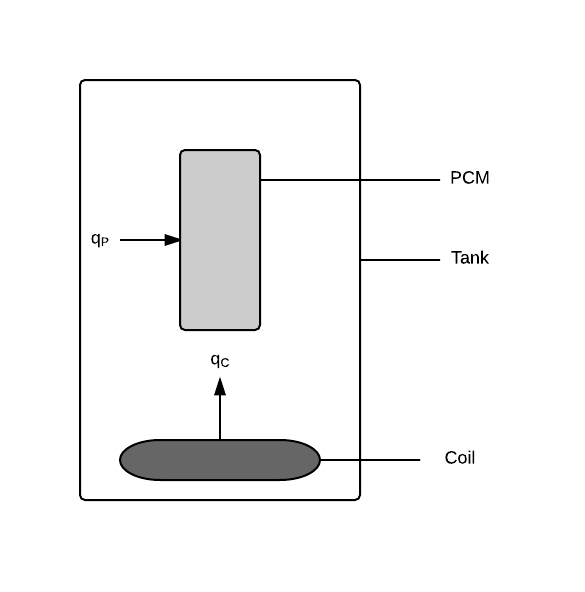
| qC |
Heat flux into the water from the coil |
\(\frac{\text{W}}{\text{m}^{2}}\) |
| qin |
Heat flux input |
\(\frac{\text{W}}{\text{m}^{2}}\) |
| qout |
Heat flux output |
\(\frac{\text{W}}{\text{m}^{2}}\) |
| qP |
Heat flux into the PCM from water |
\(\frac{\text{W}}{\text{m}^{2}}\) |
| q |
Thermal flux vector |
\(\frac{\text{W}}{\text{m}^{2}}\) |
| S |
Surface |
m2 |
| T |
Temperature |
°C |
| ΔT |
Change in temperature |
°C |
| Tboil |
Boiling point temperature |
°C |
| TC |
Temperature of the heating coil |
°C |
| Tenv |
Temperature of the environment |
°C |
| Tinit |
Initial temperature |
°C |
| Tmelt |
Melting point temperature |
°C |
| TmeltP |
Melting point temperature for PCM |
°C |
| TP |
Temperature of the phase change material |
°C |
| TW |
Temperature of the water |
°C |
| t |
Time |
s |
| tfinal |
Final time |
s |
| tfinalmax |
Maximum final time |
s |
| tmeltfinal |
Time at which melting of PCM ends |
s |
| tmeltinit |
Time at which melting of PCM begins |
s |
| tstep |
Time step for simulation |
s |
| V |
Volume |
m3 |
| VP |
Volume of PCM |
m3 |
| Vtank |
Volume of the cylindrical tank |
m3 |
| VW |
Volume of water |
m3 |
| η |
ODE parameter related to decay rate |
-- |
| π |
Ratio of circumference to diameter for any circle |
-- |
| ρ |
Density |
\(\frac{\text{kg}}{\text{m}^{3}}\) |
| ρP |
Density of PCM |
\(\frac{\text{kg}}{\text{m}^{3}}\) |
| ρPmax |
Maximum density of PCM |
\(\frac{\text{kg}}{\text{m}^{3}}\) |
| ρPmin |
Minimum density of PCM |
\(\frac{\text{kg}}{\text{m}^{3}}\) |
| ρW |
Density of water |
\(\frac{\text{kg}}{\text{m}^{3}}\) |
| ρWmax |
Maximum density of water |
\(\frac{\text{kg}}{\text{m}^{3}}\) |
| ρWmin |
Minimum density of water |
\(\frac{\text{kg}}{\text{m}^{3}}\) |
| τ |
Dummy variable for integration over time |
s |
| τPL |
ODE parameter for liquid PCM |
s |
| τPS |
ODE parameter for solid PCM |
s |
| τW |
ODE parameter for water related to decay time |
s |
| ϕ |
Melt fraction |
-- |
| ∇ |
Gradient |
-- |